A bell crank sometimes depicted as rocker arm aids in transferring bump and droop motion during vehicle translation from wheels via pushrod to suspension dampers in order to ascertain healthy ride comfort. An inboard mounted spring a push rod and a bell crank assembly.

Pushrod Bell Crank Kinematic Model 8 Download Scientific Diagram
To overcome the unequal load distribution which occurs with the reactive balance beam suspension when either driving or braking a.

. The design freedom is available due to the use of a bell crank. I was thinking why not use a pushrod that is offset either to the left or right side of the control arm so the pushrod is moving 100 vertical with the suspension. Point B represent the hinge.
Procedia Engineering 144 2016 1138 â 1149 By solving equation 2 all the forces acting on push rod at lower A-arm end as well as at bell crank end were obtained. Free Shipping On Orders Over 99. This design makes use of a push rod and bell crank to provide a more advantageous motion ratio for the shock and spring.
The push rod is connected with triangular bell crank that pivots about a. The material properties and costing of material was studied and standard Bell Crank Lever materials were identified by using PSG Design Data Book. A pull rod suspension system with a given mechanical advantage and motion ratio will be designed which will be lighter and stronger than the currently used bellcrank in the FSAE community shown in figure 1.
Thus as bell crank levers 30 rotate push rods 58 tend to move to a position perpendicular to both brake beams. During operation pneumatic pressure is applied to brake cylinder 38 causing pivots 42 and 44 to move apart rotating bell crank levers 30 about pivots 36. A bell-crank lever consists of a long arm 8 1 2 in.
In effect it should round about triple the maximum load depending on deployment angle. An inboard mounted spring a push rod and a bell crank assembly. A vertical ball governor driven by a bevel gear on the side of the reducing-spur gear operates through a bell crank the lateral movement of a disc revolving on a pin fixed in the gas and-air-valve push-rod for making a graduating or hit-and-miss charge.
If the bell-crank werent present it would have to be placed almost horizontally which would be difficult to fix and adjust. It was found that the force -Fpb acting on the bell crank by pushrod isnât coplanar with the bell crank. Movement of the cockpit controls transfers force through the cable to the bell crank which moves the control.
Bolt on Push Rod-System. Bell Crank Point A in above figure represents mounting for pull rod. Design and Analysis of Suspension Component of F1 Prototype.
All the rods are parallel to each other. Bell Crank Push Rod Design. Attach ends of other rods to the upper bell cranks that are color coded Dark Green.
The bell crank is made of mild steel. Because push rod simply transfer all the force to bell crank or rocker arm which in turn is passed on to spring and dampers. Thus the bell-crank does two jobs basically.
2 1143 Y. This article deals with design of Formula SAE Suspension by considering various loads and their simulation on each component of the system. Push-pull control rod systems and cable and pulley systems.
1 allow the shock-absorber to be placed almost vertically. Long and a short arm 4 in. Attach the lower control rods shown in the lighter green to the lower bell crank.
A-Arms Bell Crank Pushrod Ansys Spring and Dampers 1. Existing Bellcrank Design in FSAE Journal of University of Shanghai for Science and Technology ISSN. Everything You Need For Anything You Drive.
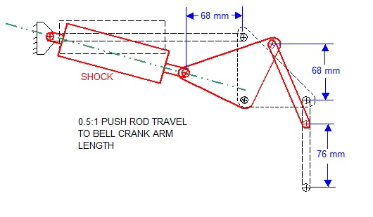
The distance between the pick-up points can be increased or decreased to either raise or lower the effectforce that the coil over has on the wheel. Long at right angles to each other. Some declare that it requires a large amount of talent on portray your very own.
The Suspension system is a device connecting the body with wheels. It seems the ideal common design has the push rod originating from the center of the lower control arm at an angle to pass the axle up to the bell crank. Now from buckling analysis we get an idea that even in worst.
In the cable and pulley system cables are connected from the control in the cockpit to a bell crank or sector. Introduction 1 What is Suspension System. Calculate the force to be applied at right angles to the end of the long arm to overcome a resistance of 40 lbf acting at 30 to the vertical of the short arm.
Shift and select both points right click on one point and then select coincident mate. The multi-link suspension has one control extra rod also called a PullRod linking the Upper end of the knuckle to the outer pivot point of the bell-crank. The bell crank shown in III-2 is basically symmetric.
Provided none of the existing components fail. Make a drawing of the arrangement. Figure III-2 shows details of the exact positioning of the components.
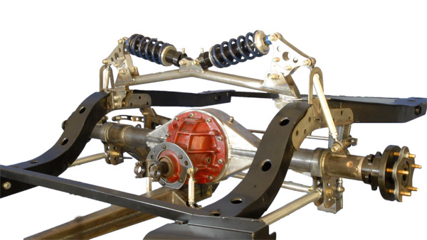
A bell crank is a pivoting mounting point that transfers the force from the push rod into the damper. Opposed to the normal type outboard suspension the inboard design transmits the wheel forces through a pushrod and bell crank to transfer the motion of the. A bell-crank lever consists of a long arm 8 1 2 in.
The bell crank is connected to the control surface. Long and a short arm 4 in. A basic representation of bell crank is described in following figure.
This research includes all design considerations calculations and implementation of various components used. An arm on the push-rod is adjustable for regulating the throw of the valve. This design makes use of a push rod and bell crank to provide a more advantageous motion ratio for the shock and spring.
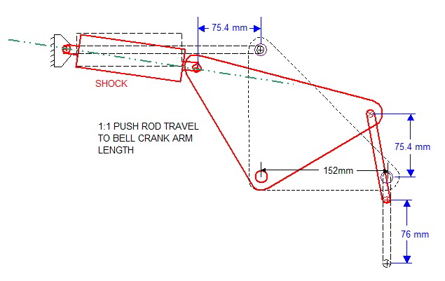
Samant Saurabh et al. The proven design is a type of inboard pushrod suspension when space is limited and the shock cannot be mounted in the most beneficial location. The bell crank designed is such that the travel of the shock-absorber is more than the travel of the push-rod.
Ad Save on Performance Pushrods by COMP Cams Trick Flow Edelbrock more. Design of Bell Crank Lever was designed by considering some properties like Density Youngs modulus Ultimate tensile strength Yield Strength Shear modulus Cost. The bell crank is also designed on the basis of suspension geometry made by taking the hard points.
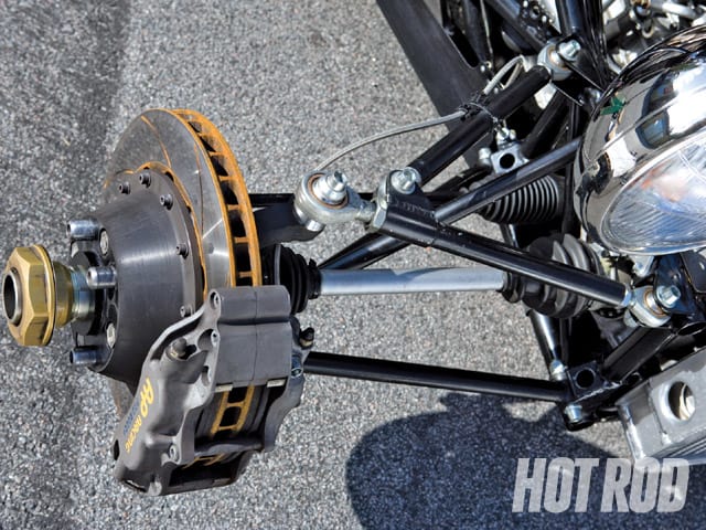
Bell crank push rod design To be a starter you can also make your individual Nail Artwork Influence employing two means. Push Rod Suspension- in this setup a push rod is placed on the Lower control arm of the Double wishbone suspension which connects the bell crank mounted on the chassis The bell crank connects to the DampersThe Vertical loads Cornering Forces are transferred and damped through the rods into the Dampers as the wheel moves during bump or cornering. Bell crank push rod.
It is the point which takes force from pull rod to be transferred further. Buying 3D decorations comprised of plastic and glue them on the nail or you can find your own personal acrylic and paint your own personal nails.

Pin On Eng Tech
Post 41 Cranking Up The Shocks
Bellcrank For Pushrod Suspension Or Shocks Off The Shelf
Bell Crank Push Rod Suspension System Youtube

Push Rod Bell Crank Suspension Super 7th Heaven
Post 41 Cranking Up The Shocks

Push Rod Bell Crank Suspension Super 7th Heaven
Awd Pushrod Front Suspension Design Automotive Suspension Engineering Eng Tips
0 comments
Post a Comment