21 st March 2011 Sakib Sarker Darlington Midrange Technical Operations MTO 2. When it does not exist design it - Sir Henry Royce 3.

Pdf Design And Analysis Of Crankshaft Used In Aerospace Applications And Comparision Using Different Materials
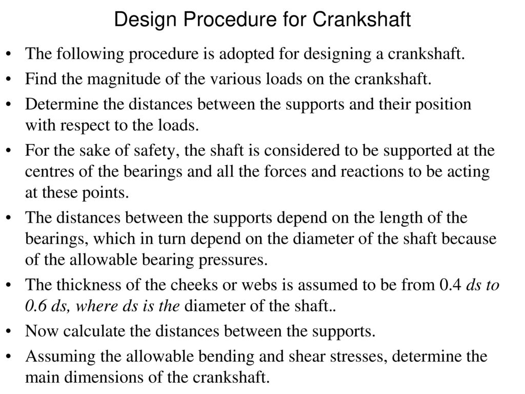
Design Procedure for Crankshaft The following procedure may be adopted for designing a crankshaft.
. Since the analysis is linear and elastic for static analysis the stress displacement and. 41 Figure 214 Flow-chart for transient stress analysis of crankshaft Payer et al 1995. Changes reciprocating motion of pistons into rotating motion to drive propeller Constructed of chrome-nickel-molybdenum- steel May be one piece or as many as three separate pieces The propeller mounts to the front of the crankshaft using a spline taper or flange The crankshaft rotates within the crankcase and is supported by main bearing journals Crankshaft throws or.
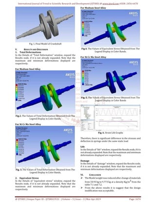
Analysis of crankshaft-cast Iron Figure- 71 Apply Boundary conditioon the crankshaft The two ends of the crankshaft is To be fixed the load 35 Mpa is applied on the top of the crankpin surface. Design of an Engine Crankshaft 1. Design of Crank Web.
2018 - 2028 - Forging is a manufacturing process. Have experience of about four decades in crankshaft grinding engine repairs and maintenance. This project aims to determine.
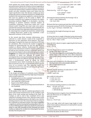
Then the results are drawn Von-misses stress induced in the crankshaft is 1583Mpa and shear stress is induced in the crankshaft is 8271Mpa. Solve and find Diameter of Crank Pin. Design of Crank Pin Torque at Crank Pin Tcr P602πN 74560 2π100 7114 N-m Force at Crank Pin Fcr Torque crank radius 71141000 75 948 N Max Force at Crank Pin Fcrm Fcr IF 9482 1896 N Diameter of Crank Pin sqrt4Fπτ sqrt41896 π50 7 mm 8 mm standard size pin.
Design and Validation of a Crankshaft 4. Crankshaft Grinding and Repair Crankshaft Grinding Services - RA Power Solutions Pvt. In all industry this technique is get much attention nowadays in Design and Analysis of Crankshaft Kevin Patel1 Darshan Rathod2 Dhaval Patel3 Vishal Patil4 Mit Patel5 Kalpan Desai6.
The crank web is designed for eccentric loading. Design and analysis of assembly of Piston Connecting rod and Crank shaft G Gopal L Suresh Kumar D Gopinathand Uma Maheshwara Raoϯ Chinthalapudi Engg College Ponnur Guntur 522124 India CBIT Hyderabad Telangana India ϯSMICH Hyderabad Telangana India Accepted 05 Feb 2016 Available online 07 Feb 2016 Vol6 No1. Steel materials are used to design the connecting rod.
Design and analysis of connecting rod using aluminium alloy 7068 t6 t6511. Mechanical and biomechanical analysis of a linear piston design for angular-velocity-based orthotic control. Solve FBD for length.
The Single Cylinder Engine - We are to design a r crank mechanism consisting of a crankshaft. Also it connects reciprocating piston to rotating crankshaft. There will be two stresses acting on the crank web one is direct compressive stress and the other is bending stress due to piston gas load Fp.
Working Model Slider Crank Solid Works 3D 2005. A connecting rod basically connects the piston to the crankshaft whilst transmitting power of the combustion from the combustion chamber to rotate the crank. P 6998 MPa.
CHARACTERISTICS OF CRANKSHAFT OF A MEDIUM SEGMENT CAR BACKGROUND The crankshaft and the connecting-rod convert the reciprocating motion of the piston into one of rotation. Determine the distances between the supports and their position with respect to the loads. Ced_ppt Ajay Tyouharia.
While in operations we have repaired over 10000 crankshafts of. Analysis is a one type of numerical analysis technique for obtain approximate solution. Take the best that exists and make it better.
The finite element analysis FEM software ANSYS is used to analyse the stress status and vibration modal for the distortion behaviour of the crank shaft. Finite element analysis FEA is performed to obtain the variation of stress at critical locations of the crank shaft using the ANSYS software and applying the boundary conditions. Global Industry Analysis 2013 - 2017 and Opportunity Assessment.
Your Mini Cooper comes equipped with various sensors that keep a tab on the functioning of the critical components in your Mini Cooper. Since the crankshaft experiences a large number of load cycles during its service life fatigue performance and durability of this component has to be considered in the design process. Know more about crankshaft grinding and crankshaft repairs - There are numerous groups in the business that offers crankshaft repairs and producing aids.
Model is imported in ANSYS 130 for analysis. P 3766 MPa Piston pin End. DESIGN AND ANALYSIS OF CYLINDER HEAD OF AN ENGINE Vishal Sapkal1 Kamal Ukey2 1Student of CAD ME Mechanical Engineering.
PowerPoint PPT presentation free to view Automotive Forging Market. Figure- 72 crankshaft voin-misses stress The maximum stress induced in the crankshaft is 1583 Mpa at the crankpin neck surface. The crank stress change model and the crank stress biggest hazard point were found by using finite element analysis and the improvement method for the crankshaft structure design was given.
Common Causes of Crankshaft Position Sensor Failure in Mini Cooper from Certified Mechanics in Spring - Mini Cooper is a very popular luxury car in the world and is known for its powerful performance and elegant design. P 7717 MPa. First of all find the magnitude of the various loads on the crankshaft.
It is very flexible as an analysis code. 42 Figure 215 Solid element model of a crankshaft Payer et al 1995. INTRODUCTION One of the important part of the combustion engine is the connecting rod and the main purpose of the connecting rod is to transfer the energy from the pistons to crankshaft and convert the linear reciprocating motion of a piston into the rotary motion of a crankshaft from the viewpoint of functionality.
P 415 MPa Piston pin End. In this project the material carbon steel of connecting rod replaced with Forged steel Connecting rod was created in CATIAV5 R19. The objective of the present work is to design and analyses of connecting rod made of Forged steel.
Slider Crank Mechanism PowerPoint PPT Presentations. Figure 212 A finite element crankshaft model Henry et al 1992. DESIGN AND ANALYSIS OF CRANKSHAFT WITH DIFFERENT COMPOSITE PPTpptx - Free download as Powerpoint Presentation ppt pptx PDF File pdf Text File txt or view presentation slides online.
Converted to mechanical power on to the crankshaft and part of it is wasted as heat losses through exhaust gases and heat transfers to the surroundings. Thickness of crank web Tst 065 dc 635 dc. The crankshaft is made very stiff since it is subjected to severe and varying twisting and bending stresses due to the combustion pressures and also to the.
62 THERMAL ANALYSIS OF CRANKSHAFT EXISTING MODEL Fig14 Thermal analysis for crankshaft 17. DESIGN AND ANALYSIS OF A. 41 Figure 213 Stress prediction of crankshaft using a neural network structure Shiomi and Watanabe 1995.
Analysis of water hammer forming on the sheet metal 2.

Crankshaft Ppt
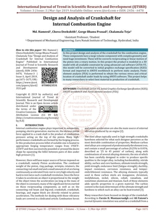
Design And Analysis Of Crankshaft For Internal Combustion Engine

Design And Analysis Of Crankshaft With Different Composite Pdf Deformation Engineering Young S Modulus

Ppt Connecting Rods Powerpoint Presentation Free Download Id 1086711

Ppt Crankshafts Crankshaft Design The Crankshaft Converts Th Powerpoint Presentation Free To View Id 3e3c67 Zwiwz
Design And Analysis Of Crankshaft For Internal Combustion Engine
Mechanical Design Of Engine Parts Ppt Download
Design And Analysis Of Crankshaft For Internal Combustion Engine
0 comments
Post a Comment